
Welcome to Clean Vehicles 101!
Presented by 352 Innovation
THIS is THE place to learn about clean vehicles - what they are, how they work and what happens when they don't.
This page hosts snippets plucked from the Clean Vehicle Roadmap | The Path to Clean Vehicle Service and articles written by 352 Innovation for Vehicle Service Pros, where we are proud to be a Guest Blog Contributor!
Note: Links to image sources are provided in the caption. Sources used to help create this article, and the Roadmap, are embedded throughout. Roadmap Sections have a separate Works Cited List, available for download, of all sources used. Section I Works Cited List is available for download (end of post)
★★★★★★★★★★★★★★★
H2ICE Under Construction
★★★★★★★★★★★★★★★
═══════
Hydrogen Combustion Engines (H2ICE)
═══════
H2ICE CAN and WILL Advance GLOBAL Decarbonization Goals
The first Internal Combustion Engine (ICE) ignited its first power stroke on a “dirty” hydrogen (H2) gas mix.
In 1807, Swiss engineer François Isaac de Rivaz invented a Spark-Ignition (SI) hydrogen internal combustion engine on a dirty hydrogen gas mix. The first Hydrogen Combustion Engine (H2ICE) - January 30, 1807 patent was issued decades before the fossil fuel engine.
During the development of the fossil fuel fired combustion engine, combustion was difficult to control and the volatility of the fossil fuel used made it dangerous enough that they switched to running the engine on a hydrogen gas mix!
Herr Otto, blessed us with thy four-stroke cycle, also helped to invent the carburetor and, here we are, full circle, back to hydrogen gas!
Nicolaus Otto worked with Gottlieb Daimler and Wilhelm Maybach (1879-1885) to develop the first compressed charged, four-stroke cycle engine and the first float-fed type design carburetor with the ability to atomize the fuel via an atomizer nozzle.
That necessity brought us the carburetor and now, nearly two hundred years later, we have come full circle… almost....
Banning the sale of new vehicles powered by internal combustion engines is shutting out a market that will bring tremendous opportunity for economic growth in America, and globally, save and create jobs, further reduce emissions, and improve public opinion of Zero Emission Vehicles (ZEV).
1: Retain and Create Automotive Industry Jobs
H2ICE will keep and create jobs for the automotive industry. Vehicle and engine manufacturers, aftermarket parts, independent shops, auto mechanics and engine builders.
2: Rapid Decarbonization
H2ICE will rapidly reduce emissions across the globe far faster than Zero Emission Vehicles (ZEV) can be built and sold.
3: Drive Hydrogen Demand
H2ICE will drive hydrogen (H2) sales and reduce demand for liquid petroleum. Driving H2 infrastructure faster than Hydrogen Fuel Cell Vehicles (HFCV) can be produced and sold.
H2ICE can operate on a wide range of hydrogen gas mix quality, allowing sales of gaseous hydrogen that cannot be sold for use in Hydrogen Fuel Cell Vehicles (HFCV) since hydrogen fuel cells require gaseous hydrogen quality of 99%.
4: Negligible Cybersecurity Risk
H2ICE does not have the cybersecurity risk that electric powertrain vehicles have. Electric powertrains rely on computer software to operate sophisticated control systems. While mechanical powertrains also rely on software-based control systems to operate, they do not require access to the internet, nor can these control systems be hijacked.
5: Operational Over Wide Range of Hydrogen Gas Quality
H2ICE can run on a “dirtier” – i.e., less pure H2 gas – than fuel cells, which allows for hydrogen production, storage, and infrastructure to stabilize their hydrogen gas quality.
6: Interim Option for Rapid Decarbonization
H2ICE is an interim option to reduce emissions, allow time for development of clean energy, allow time for workforce training and development, and improve public opinion of clean vehicles. And a long-term solution to keep classic cars classic and allow for the operation of combustion engine equipped vehicles long after fossil fuels are no longer sold.
7: Rapid Fleet Decarbonization – Cheaper Alternative to Fleet Replacement
H2ICE conversions on small business fleet vehicles offers a significantly less costly means to reduce fleet emissions.
H2ICE in the heavy haul transportation sector is being driven by engine manufacturers like Cummins, Volvo, Daimler, MAN, MAHLE, and more.
★★★★★★★★★★★★★★★★★★★★★★★★★★★★★★
I.A.vi Battery Electric Vehicle (BEV)
Powertrain Hardware, Operation, Thermal Management, and Charging Options
═══════════════════
Battery Electric Vehicles
═══════════════════
Blog Post #1: Overview of the Battery Electric Vehicle (BEV) Powertrain Hardware,
Operation, and an Overview of the Charging Process | Oct 13, 2025
Enjoy this sneak-peek of what The Clean Vehicle Roadmap has to offer!
Section §I: Clean Vehicle Powertrains | Electrical & Battery Terms | H2ICE
§I.A.vi: Battery Electric Vehicle (BEV)
I.A.vi: Battery Electric Vehicle (BEV)
Battery Electric Vehicles (BEV) are configured with a plug port and/or wireless capable for charging the primary power source – the High Voltage Battery (HVB) aka the traction battery. Some concept cars are developing the use of supercapacitors to act as temporary batteries, like the Lamborghini concept supercar Terzo-Millennio that was developed with Massachusetts Institute of Technology (MIT) engineers. Others, like Croatian based Rimac Automobili, have developed next-level traction control in their Nevera supercar, with the traction motor inside the hub of the wheel, similar to Lamborghini.
I.A.vi.a: Battery Electric Vehicle (BEV) Powertrain Overview
The basic function is the High Voltage Battery (HVB) provides the electrical energy to power all onboard systems, which include power management, Battery Management System (BMS), Onboard Charger (OBC), DC-DC converters, inverters, electric motors, and traction motors, and other power electronics. To replenish the consumable energy – electricity – the vehicle is plugged into Electric Vehicle Supply Equipment (EVSE) for charging via plug/port or by wireless charging.
I.A.vi.a.i.a: Battery Electric Vehicle (BEV) Powertrain Configuration | Alternative Fuels Data Center (AFDC)
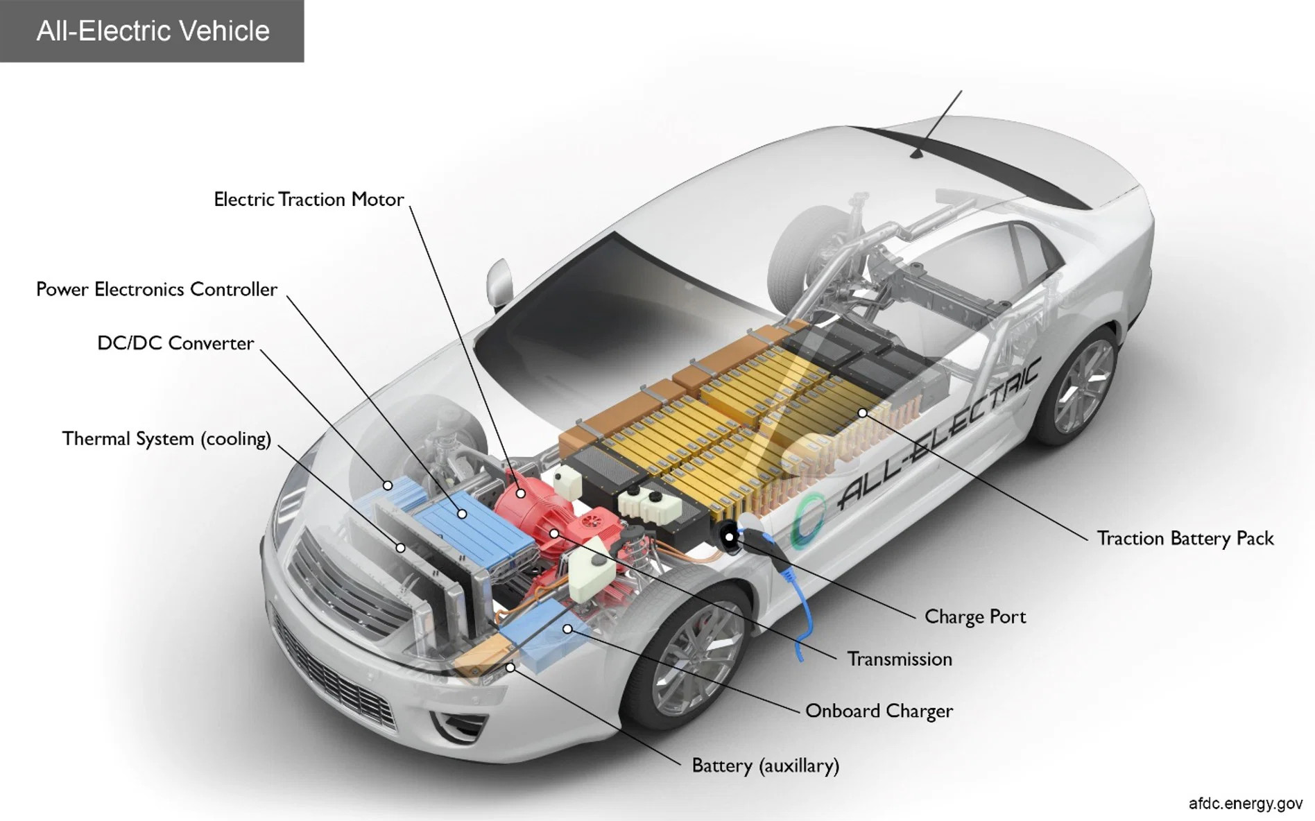
Figure 1: Typical Battery Electric Vehicle (BEV) Powertrain Configuration | Alternative Fuels Data Center (AFDC)
I.A.vi.a.i.b: Battery Electric Vehicle (BEV) Powertrain Hardware Graphic | EV Engineering Online
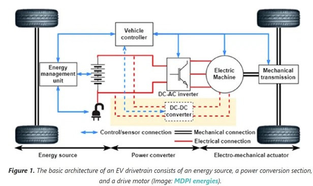
Figure 2: Battery Electric Vehicle (BEV) Powertrain Hardware Graphic | EV Engineering Online | J Shepard | Oct 2023 | MDPI energies
I.A.vi.b: High Voltage Battery (HVB) aka Traction Battery
Battery Electric Vehicles (BEV) rely on a High Voltage Batteries (HVB) as their primary power source to move the vehicle. Most of these High Voltage Batteries (HVB) are Lithium (Li) based – Lithium-ion Batteries (LiB) – and lithium metal has inherent instabilities. LiBs have a narrow window of stable operation, LiB safety, and their continued development, is an issue being addressed by the highest levels of government and researchers across the globe.
Battery packs are typically assembled by packing battery cells into modules which are then assembled into the battery pack used in EVs. There are various battery pack architecture configurations available for Electric Vehicle (EV) battery packs, as shown in Figure 3.
Battery cells may be arranged in series and parallel configurations to optimize the power delivery and charging speeds. Battery cells come in various shapes and chemistries – like Lithium (Li), Iron (Fe), Phosphate (PO4) - LFP – and these material properties play a critical role in battery stability, reliability, and performance. Battery cell balancing is a critical function for performance, reliability, and safety.
I.A.vi.b.i: Electric Vehicle Battery Pack Configurations
I.A.vi.b.i.a: Electric Vehicle Battery Pack Configurations | Battery Technology
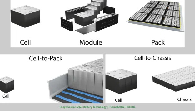
Figure 3: Various Battery Pack Architecture Configurations | 2023 Battery Technology | T Campbell & F Billotto
Battery packs and sub-structure(s) are subjected to SAE International (SAE) guidelines and government regulations and are continuously being evaluated and updated as battery and charging technology improves. SAE J2289: Electric-Drive Battery Pack System: Functional Guidelines.
A critical powertrain component – for performance, lifespan, and safety – is the Battery Management System (BMS). This control system will modulate the Thermal Management System (TMS) to operate a series of pumps and heaters/coolers to move the specially formulated liquid coolant through the heat exchanger(s) and use it to maintain the LiB at its most optimum temperature for the given operation, like charging level and power output.
Excessive heat has been shown to rapidly degrade LiBs, making BTMS a critical system for ensuring the battery meets the lifespan requirements, that are being rolled out by governments across the globe, like California wanting to require that the “B” in BEV maintains at least 80% of its certified test-cycle range for 15-years or one-hundred and fifty thousand miles. Thermal management of the HVB is often one loop of 2 to 3 loop systems to provide thermal management to all the power electronics, motors, and other hardware.
I.A.vi.b.i.b: Examples of Charging Plugs and Adapters | Battery Power Tips | ChargeX Consortium | COMEMSO
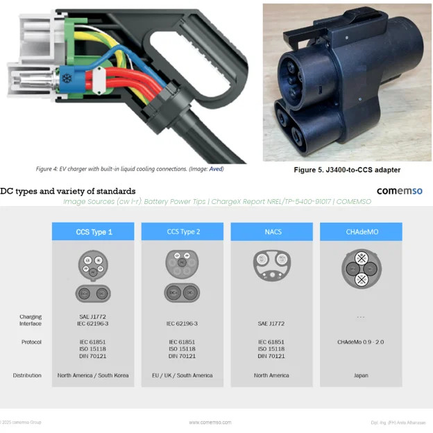
Figure 4: Charging Plug Adapters | ChargeX Consortium NREL/TP-5400-91017 | COMEMSO
I.A.vi.c: Battery Electric Vehicle (BEV) Charging Overview
Battery Electric Vehicles (BEV) use a port/plug configuration to connect the charging equipment, known as Electric Vehicle Supply Equipment (EVSE) aka charging stations, to the vehice.
Charging equipment comes in various levels of charging energy types and energy levels, like household Alternating Current (AC), like the typical home installation, called Level I charging.
Charging levels go up to Level 3 for Direct Current Fast Charge (DCFC), which can take a battery from 10% State of Charge (SoC) to 80% SoC in about an hour.
Charging can also take place via Regenerative Braking through the vehicle’s internal battery charging circuit. Regenerative brakng (aka regen) has specific criteria surrounding whether it activates or not.
If equipped, the vehicle will turn the traction motors into generators (or alternators, if AC) and will recharge the traction battery IF the criteria is met.
Criteria include battery SoC, vehicle speed, and any manual settings controlled by the driver. Many owners’ manuals will outline the details of the regenerative braking operation.
I.A.vi.c.i: Megawatt Charging System (MCS)
Agencies like SAE International (SAE) and the US Department of Energy (DOE) with the National Labs, and the global agency, CharIN, are rolling out Megawatt Charging Systems (MCS) which can deliver charging at up to 3,000A! Current DCFC delivers 80-300A. The global consortium Charging Interface Initiative (CharIN) is helping to advance MCS and issued a May 2025 White Paper detailing the hardware, software, electrical, and thermal requirements needed to safely support MCS plug charging at such enormous levels of energy.
I.A.vi.c.i.a: Fast Charging Energy Comparison Table | Charged EV Magazine Webinar | Schaltbau of North America | Sept 2025 Webinar
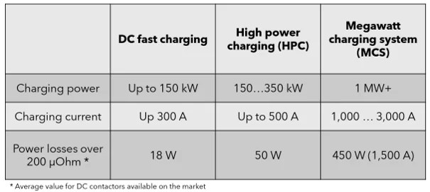
Figure 5: Fast Charging Energy Comparison Table | Charged EV Magazine Webinar | Schaltbau of North America | Sept 2025
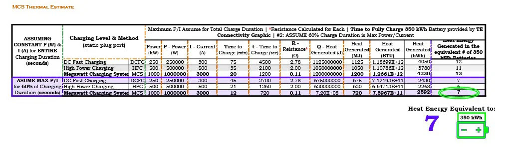
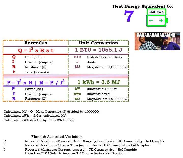
Figure 5a: Estimated Heat Energy Generated from Various Fast Charging Methods, Shown in Equivalence to 350 kWh Battery Energy | Calculations by 352 Innovation
I.A.vi.c.ii: Charging Plugs, Adapters, and ChargeX
To connect the vehicle to the charging station, a plug is used, and as of 2025, there are currently five different plug designs, and agencies, like SAE International (SAE), are rolling out the plug selected to become the industry standard plug design.
North American Charging System (NACS) is the new plug standard, developed by Tesla. SAE issued SAE J3400: North American Charging System (NACS) for Electric Vehicles to support this roll out with design standards and safety requirements.
For now, adapters are required to be used at public charging stations that do not match the stock plug.
Adapters rarely have any thermal management built into their housings, and CharIN explicitly stated, in the above-mentioned 2025 White Paper, that adapters should NOT be used with MCS.
Joint Office of Energy and Transportation (JOET) created the ChargeX Consortium to improve charging infrastructure. From the user experience to reliability and safety. They issued a safety report citing the issues with adapter hardware, namely the heating issue and the danger of their failure.
DOE/GO-102024-6398 | NREL/TP-5400-91017: ChargeX Consortium Recommended Actions to Improve Adapter Safety
JOET also formed the Electric Vehicle Working Group (EVWG) to address cybersecurity risk surrounding charging infrastructure and protecting the grid.
JOET is also supporting the roll-out of the NACS standardized plug, issued a press release:
Joint Office of Energy and Transportation Continues to Advance an EV Charging Network That Works for All Consumers With Support for the Newly Released SAE J3400 EV Coupler Recommended Practice
I.A.vi.c.iii: Thermal Management for Charging Equipment and Battery Electric Vehicles
Power - P (W) = Current^2 – I^2 (ampere) x Resistance - R (ohms)
P = I^2 x R
From Figure 5 (above), we can see just how much heat can be generated from the internal resistance created when charging at 1MW of power and 3,000A for those twenty-minutes.*
Q = I^2 x R x t
HEAT - Q (Joules) = Current^2 – I ^2 (ampere) x Resistance - R (ohms) x time - t (seconds)
Using data from Figure 6, the amount of heat energy generated, during that 20-minute charging period, is the equivalent of SEVEN – 7! – 7 x 350 kWh batteries!!
*Charging, at any level, does not maintain maximum power/current for the entire duration, and this time off maximum power/current can vary from level to level and vehicle to vehicle since the vehicle is in communication with the charging station to prevent overcharging and modulating power levels based on heat and the charging algorithm.
Thermal management is just as critical for safe thermal managment of the charging equipment, as it is for safe operation of the High Voltage Battery (HVB), and can effect the charging algorithm because the charging process generates a LOT of heat – and the higher the level, the higher the heat.
Cables used at Direct Current Fast Charge (DCFC) stations often have liquid cooling flowing through the cable itself (ref top left image in Figure 3) to draw heat out of the cable.
The Battery Electric Vehicle (BEV) will use the Battery Management System (BMS) to set the battery at an optimum temperature, and it will also perform some thermal management on the supporting power electronics, like the Onboard Charger (OBC).
The OBC is used to rectify the incoming Alternating Current (AC) power to the Direct Current (DC) power required by the battery. During DCFC, the OBC is by-passed, which contributes to the fast charging because the OBC can be a limiting factor in the speed of AC charging, based on the speed the OBC can rectify the current.
The BEV control system will prep the battery and charging circuit for DCFC by activating the Pre-Charge Circuit. Systems like Pre-Charge and the BMS are designed to protect the HVB, ensure a long lifespan, high reliability, and safe operation.
I.A.vi.c.iii.a: Electric Vehicle (EV) Charger Types | TE Connectivity
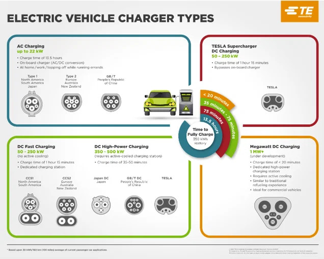
Figure 6: EV Charger Types | Addressing the Time to Charge Industrial & Commercial Transportation Vehicles | TE Connectivity White Paper | Feb 2023
I.A.vi.c.iv: Wireless Charging
Wireless charging of Electric Vehicles (EV) is coming! Stationary and in-road dynamic Wireless Power Transfer (WPT)!
SAE International (SAE) began working on wireless charging possibilities with multiple industry partners in 2007. Their testing and efforts to standardize wireless performance across countries and manufacturers, has brought this technology to be a very real infrastructure upgrade and improve vehicle charging safety for all the associated products in the next few years.
SAE J2954: Wireless Power Transfer (WPT) for Light-Duty Plug-in Electric Vehicles and Alignment Methodology
AND
SAE J2836/6: Use Cases for Wireless Charging Communication for Plug-in Electric Vehicles
AND for MEGAWATT (ref Figures 5, 6 and §!.A.vi.c.i) SAE has been released
SAE J3271: SAE Megawatt Charging System (MCS) for Electric Vehicles
I.A.vi.c.iv.a: Wireless Power Transfer (WPT) Operation Graphic | IEEE ACCESS
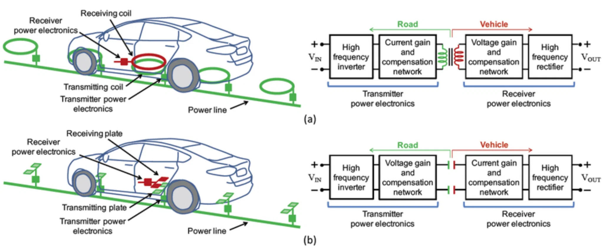
Figure 7: Graphical Depiction of In-Road Wireless Power Transfer (WPT) | IEEE Access 2019 | A Adib
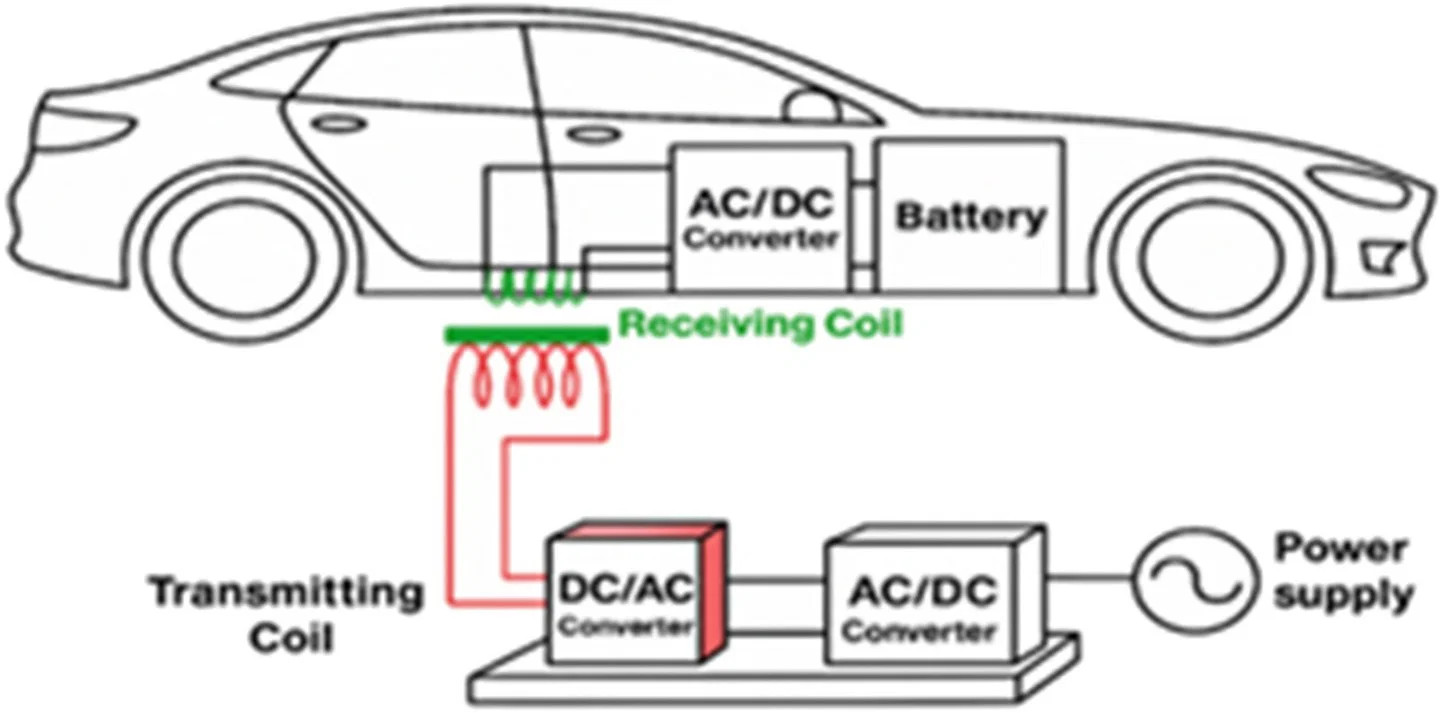
Figure 8: A Comprehensive Review of Vehicle-to-Grid V2G Technology: Technical, Economic, Regulatory, and Social Perspectives | Science Direct | MMR Ahmed | Jul 2025
═══════════════END OF POST═══════════════
═══════════════
═══════════════
Enjoy this post?
This post is a preview of the type of content quality that the Clean Vehicle Roadmap brings to your fingertips!
Sign up today and get 25% OFF!!
Let the Roadmap help you find YOUR Path to Clean Vehicle Service!!
15-Day Trial for $15 - CLICK HERE
DISCLAIMER
This page is for information and educational purposes only. Links to all sources used to help create this page are embedded throughout this page. The Works Cited List is available for free download. 352 Innovation, its subsidiaries, and/or employees are not liable for any program participation and/or changes in program details since the writing of this document. This information is provided and updated in good faith and to the best of our ability. All figure images have been borrowed from publicly available sources and links to the image source are embedded in captions and listed in the Works Cited document. 352 Innovation, its subsidiaries, and/or employees are not liable for the consequences of any decisions made based on the information provided within this and/or any additional documents affiliated with the service referred to as Roadmap to the Clean Vehicle World and/or any additional services offered by 352 Innovation or any subsidiaries. Refer to the websites linked and listed in the Works Cited document for the most up to date information. 352 Innovation is an active member of SAE International (SAE), American Society of Mechanical Engineers (ASME), Alliance for Renewable Clean Hydrogen Energy Systems (ARCHES), Automotive Service Excellence (ASE), and ASE Training Managers Council (ATMC).

© Copyright 352 Innovation, LLC
If you are experiencing website issues please contact us - support@352innovation.com